- 您现在的位置:买卖IC网 > Sheet目录218 > CUB5COM1 (Red Lion Controls)RS485 SERIAL COMMO CARD
�� �
�
�Sending� Serial� Commands� and� Data�
�When� sending� commands� to� the� meter,� a� string� containing� at� least� one�
�command� character� must� be� constructed.� A� command� string� consists� of� a�
�command� character,� a� value� identifier,� numerical� data� (if� writing� data� to� the�
�meter)� followed� by� a� command� terminator� character,� *� or� $.�
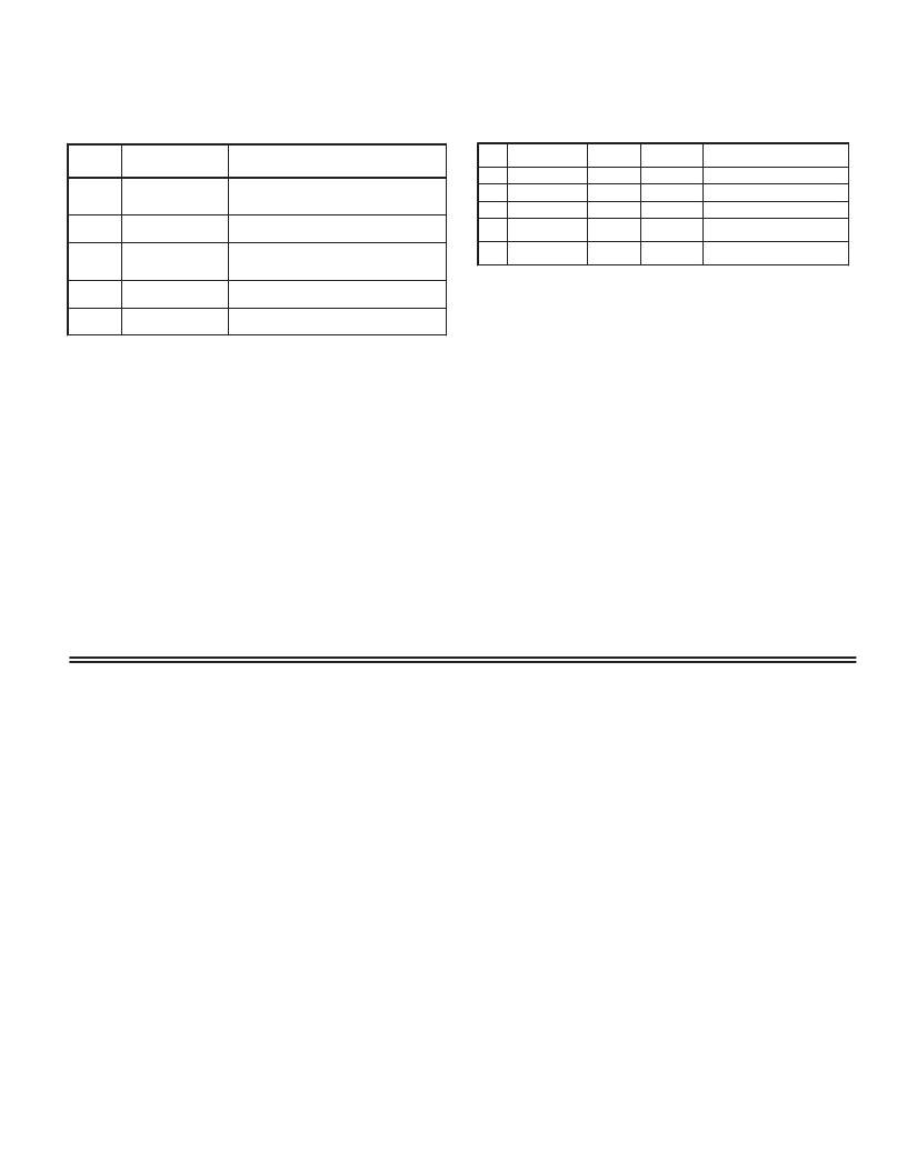
�Command� Chart�
�Register� Identification� Chart�
�Analog� Models� -� CUB5V,� CUB5I,� CUB5P,� CUB5TC,� CUB5RT�
�Command� Description�
�Notes�
�ID�
�Value� Description� MNEMONIC�
�Applicable�
�Commands�
�Transmit� Details� (T� and� V)�
�N�
�Node� (meter)�
�Address� Specifier�
�Address� a� specific� meter.� Must� be� followed� by�
�one� or� two� digit� node� address.� Not� required�
�when� node� address� =� 0.�
�A�
�B�
�C�
�Input�
�Maximum�
�Minimum�
�INP�
�MAX�
�MIN�
�T�
�T,� R�
�T,� R�
�5� digit�
�5� digit�
�5� digit�
�Transmit� Value� (read)�
�T�
�V�
�Read� a� register� from� the� meter.� Must� be�
�followed� by� a� register� ID� character.�
�Write� to� register� of� the� meter.� Must� be�
�Value� Change� (write)� followed� by� a� register� ID� character� and�
�D�
�E�
�Setpoint� 1�
�(Reset� output� 1)�
�Setpoint� 2�
�(Reset� output� 2)�
�SP1�
�SP2�
�T,� R,� V�
�T,� R,� V,�
�5� digit� positive/4� digit� negative�
�5� digit� positive/4� digit� negative�
�R�
�P�
�Reset�
�Block� Print� Request�
�(read)�
�numeric� data.�
�Reset� a� register� value� or� setpoint� output.�
�Must� be� followed� by� a� register� ID� character�
�Initiates� a� block� print� output.� Registers� in� the�
�print� block� are� selected� in� Print� Options.�
�Command� String� Examples:�
�1.� Node� address� =� 17,� Write� 350� to� the� setpoint� 1� value�
�String:� N17VD350*�
�2.� Node� address� =� 5,� Read� input,� response� time� of� 50� msec� min�
�String:� N5TA*�
�1-9�
�Command� String� Construction�
�The� command� string� must� be� constructed� in� a� specific� sequence.� The� meter�
�does� not� respond� with� an� error� message� to� illegal� commands.� The� following�
�procedure� details� construction� of� a� command� string:�
�1.� The� first� 2� or� 3� characters� consist� of� the� Node� Address� Specifier� (N)� followed�
�by� a� 1� or� 2� character� node� address� number.� The� node� address� number� of� the�
�meter� is� programmable.� If� the� node� address� is� 0,� this� command� and� the� node�
�address� itself� may� be� omitted.� This� is� the� only� command� that� may� be� used� in�
�conjunction� with� other� commands.�
�2.� After� the� optional� address� specifier,� the� next� character� is� the� command�
�character.�
�3.� The� next� character� is� the� register� ID.� This� identifies� the� register� that� the�
�command� affects.� The� P� command� does� not� require� a� register� ID� character.� It�
�prints� all� the� active� selections� chosen� in� the� Print� Options� menu� parameter.�
�4.� If� constructing� a� value� change� command� (writing� data),� the� numeric� data� is�
�sent� next.�
�5.� All� command� strings� must� be� terminated� with� the� string� termination�
�characters� *� or� $.� The� meter� does� not� begin� processing� the� command� string�
�until� this� character� is� received.� See� Command� Response� Time� section� for�
�differences� in� meter� response� time� when� using� the� *� and� $� terminator.�
�Receiving� Data� From� The� Meter�
�Data� is� transmitted� from� the� meter� in� response� to� either� a� transmit� command�
�(T),� a� block� print� request� command� (P)� or� a� User� Input� print� request.� The�
�response� from� the� meter� is� either� a� full� field� transmission� or� an� abbreviated�
�transmission,� depending� on� the� selection� chosen� in� Module� 5.�
�Full� Field� Transmission�
�Byte� Description�
�1,� 2� 2� byte� Node� Address� field� [00-99]�
�3� <SP>� (Space)�
�3.� Node� address� =� 0,� Reset� Setpoint� 1� output�
�String:� RD*�
�4.� Node� address� =� 31,� Request� a� Block� Print� Output,� response� time� of� 2� msec� min�
�String:� N31P$�
�Transmitting� Data� to� the� Meter�
�Numeric� data� sent� to� the� meter� must� be� limited� to� transmit� details� listed� in� the�
�Register� Identification� Chart.� Leading� zeros� are� ignored.� Negative� numbers�
�must� have� a� minus� sign.� The� meter� ignores� any� decimal� point� and� conforms� the�
�number� to� the� scaled� resolution.� (For� example:� The� meter� ’s� scaled� decimal� point�
�position� is� set� for� 0.0� and� 25� is� written� to� a� register.� The� value� of� the� register� is�
�now� 2.5.� In� this� case,� write� a� value� of� 250� to� equal� 25.0).�
�Note:� Since� the� meter� does� not� issue� a� reply� to� value� change� commands,� follow�
�with� a� transmit� value� command� for� readback� verification.�
�The� end� of� the� response� string� is� terminated� with� a� <CR>� and� <LF>.� After� the�
�last� line� of� a� block� print,� an� extra� <SP>,� <CR>� and� <LF>� are� added� to� provide�
�separation� between� the� print� blocks.�
�Abbreviated� Transmission�
�Byte� Description�
�9� byte� data� field,� 7� bytes� for� number,� one� byte� for� sign,� one�
�byte� for� decimal� point�
�10� <CR>� (carriage� return)�
�4-6�
�7-15�
�16�
�17�
�18�
�19�
�20�
�3� byte� Register� Mnemonic� field�
�9� byte� data� field;� 7� bytes� for� number,� one� byte� for� sign,� one� byte� for�
�decimal� point�
�<CR>� (carriage� return)�
�<LF>� (line� feed)�
�<SP>*� (Space)�
�<CR>*� (carriage� return)�
�<LF>*� (line� feed)�
�11� <LF>� (line� feed)�
�12� <SP>*� (Space)�
�13� <CR>*� (carriage� return)�
�14� <LF>*� (line� feed)�
�*� These� characters� only� appear� in� the� last� line� of� a� block� print.�
�The� abbreviated� response� suppresses� the� node� address� and� the� register�
�mnemonic,� leaving� only� the� numeric� part� of� the� response.�
�*� These� characters� only� appear� in� the� last� line� of� a� block� print.�
�The� first� two� characters� transmitted� are� the� meter� address.� If� the� address�
�assigned� is� 0,� two� spaces� are� substituted.� A� space� follows� the� meter� address� field.�
�The� next� three� characters� are� the� register� mnemonic,� as� shown� in� the� Register�
�Identification� Chart.�
�The� numeric� data� is� transmitted� next.� The� numeric� field� (bytes� 7� to� 15)� is� 9�
�characters� long.� When� a� requested� display� value� exceeds� the� meter� ’s� display�
�limits,� decimal� points� are� sent� in� place� of� numerical� data� to� indicate� a� display�
�overrange.�
�The� remaining� 7� positions� of� this� field� consist� of� a� minus� sign� (for� negative�
�values),� a� floating� decimal� point� (if� applicable),� and� five� positions� for� the�
�requested� value.� The� data� within� bytes� 9� to� 15� is� right-aligned� with� leading�
�spaces� for� any� unfilled� positions.�
�3�
�Meter� Response� Examples� (Analog� models):�
�1.� Node� address� =� 17,� full� field� response,� Input� =� 875�
�17� INP� 875� <CR><LF>�
�2.� Node� address� =� 0,� full� field� response,� Setpoint� 1� =� -250.5�
�SP1� -250.5<CR><LF>�
�3.� Node� address� =� 0,� abbreviated� response,� Setpoint� 2� =� 250,� last� line� of� block�
�print� 250<CR><LF><SP><CR><LF>�
�发布紧急采购,3分钟左右您将得到回复。
相关PDF资料
CUB5IB00
DC METER RED/GREEN BKLT
CUB5PB00
PROCESS METER RED/GREEN BKLT
CUB5RTR0
RTD METER REFLECTIVE
CUB5TCB0
METER PANEL LCD THERMOCOUPLE RED
CUB5USB0
USB OPTION CARD
CUB5VR00
METER LCD DC VOLT 8DIGIT
CUR-3285-MB
BOX ABS 8.25X5.15X3.13" BLACK
CUR-3286-MB
BOX ABS 10.15X6.15X3.13" BLACK
相关代理商/技术参数
CUB5COM2
功能描述:RS232 SERIAL COMM CARD FOR CUB5 RoHS:是 类别:工业控制,仪表 >> 配件 系列:* 标准包装:1 系列:Aero-Motive® 130117 附件类型:拖车带 适用于相关产品:标准盒式跟踪系统 其它名称:WM6183
CUB5IB00
功能描述:DC METER RED/GREEN BKLT RoHS:是 类别:工业控制,仪表 >> 仪表 - 面板,数字 系列:* 标准包装:12 系列:* 其它名称:Q7072030
CUB5IB00 CALIBRATED
制造商:Red Lion Controls 功能描述:DIGITAL PANEL METER MODEL CUB5 WITH CERTIFICATE OF CALIBRATION
CUB5IR00
功能描述:DC METER REFLECTIVE DISP RoHS:是 类别:工业控制,仪表 >> 仪表 - 面板,数字 系列:* 标准包装:12 系列:* 其它名称:Q7072030
CUB5OEMS
制造商:Red Lion Controls 功能描述:PROGRAMMING KIT FOR SOFTWARE
CUB5PB00
功能描述:PROCESS METER RED/GREEN BKLT RoHS:是 类别:工业控制,仪表 >> 仪表 - 面板,数字 系列:* 标准包装:12 系列:* 其它名称:Q7072030
CUB5PR00
功能描述:PROCESS METER REFLECTIVE RoHS:是 类别:工业控制,仪表 >> 仪表 - 面板,数字 系列:* 标准包装:12 系列:* 其它名称:Q7072030
CUB5R000
功能描述:COUNTER/RATE IND DUAL REFL DISPL RoHS:是 类别:工业控制,仪表 >> 计数器 系列:CUB5 其它有关文件:Declaration of Conformity 标准包装:1 系列:99766 计数速率:25Hz 数字/字母数:5 输入类型:机电式脉冲 输出类型:- 电源电压:24V 显示器类型:十进制拨轮